Wednesday, February 17, 2010

Tone Mapping

Tone mapping is the process of taking lighting values and converting those to display values. By using different equations we can get different effects in this process. The first three images below were done using Reinhard's model, using a constant key value but adjusting the maximum luminance.


The fact that these three images are similar has to do with the nature of the mapping here. The mapping equations attempts to convert the lighting units to a fixed luminance level for display. In essence, since the entire scene has the same lighting contrast in each of these images (just different absolute lighting levels) they all map to similar display units.

The image below adjusts the key value to create a brighter image. The lighting units here are being converted to brighter display units thanks to a higher key value.


Finally, we see an even brighter image below. This image used a very high key value which created an over-exposed look. Key values can either be manually selected, or they can be pulled from the image itself. A pixel position may be used and the luminance key read from that pixel position.

Thursday, February 11, 2010

RenderMan Stuffs

So, here's some renderman images. They are even less impressive than my raytracing images. That's because renderman is complicated and when just starting out your results tend to be... underwhelming. Trust me, prman (Pixar's implementation of RenderMan) has way more power than my raytracer.


Wednesday, February 10, 2010

Success in the end

Taking a last stab at it I got refraction working. The only problem is that total internal reflection is not quite working. I'm not too concerned about that. In general it looks pretty good. The problem was in the refraction ray calculation.


Next Steps

I'm still having trouble getting my transmission looking correct because I've been focused on the occlusion culling. I've figured out what I'm going to do to thread the system, but I don't think I'll be able to finish before the end of the quarter.

I will be threading the system by calculating the occlusion for the next frame while the current frame is rendering. Essentially, I'll be delaying the system by one frame so that the occlusion mapping can go head and do its rasterizations on the next frame. This system is very similar to how object-space motion blur is done. Transformation matrices are stored from last frame and used for rendering by the transformation matrices for this frame are used for occlusion culling.

Discussing this with the Ogre team led me to the current plan. I will use the existing WorkQueue system in Ogre but I need to augment it so that custom thread pools can be created. The thread pool for the occlusion system will be reserved for per-frame tasks. Since both this and the double-buffered transformation system are considerable changes I doubt I can finish them in time.

Instead my plan is to create a hierarchical z-buffer. In theory this can lower the amount of rasterization needed. This combined the octree should be able to speed up a lot of calculations. The rest of the quater will focus on creating good example scenes and doing performance testing of the non-threaded system.

Tuesday, February 2, 2010

Transmission First Try

This time we need to put in transmission (transparent surfaces with refraction). When a surface is hit, the raytracer needs to create a new ray and trace it through the transparent surface and calculate an exit direction. That exit direction will be traced and then the color from that bent ray will influence the color of the transparent surface. For this first attempt only the first refracted hit is calculated, which results in a very flat looking refracted surface.


As you can see the effect isn't quite finished. The blue sphere does not look transparent. It is not nearly as good as the reflection effect on the orange sphere.

Wednesday, January 27, 2010

Reflection and Ray Count Explosion


This time around is reflection. Not much to say here. When the ray hits a reflected surface it spawns a new ray in the reflected direction. There's a couple levels of recursion here. That could easily be changed. Obviously we don't want infinite recursion, since that could cause infinite loops.


This image shows a new technique. The blue sphere casts a cone of reflection rays to pick up diffusely reflected light from the scene. There's only 32 samples being used, no anti-aliasing, and the image is 200x200 pixels. That's because the render time is getting a little high.

The problem here is that with raytracing, each time we add an effect (reflection, diffuse reflections, ambient occlusion, etc.) we need to cast more rays. Each time we get closer to realism we need to cast tons of new rays. At this point, all of the light features we are trying to capture is causing us to cast millions of rays into the scene.


Tuesday, January 19, 2010

Fast Occlusion Culling: Midterm Update

The biggest starting hurdle in the project has been replacing the old software rasterizer with a new one. The old rasterizer was created using an open-source project called TinyGL. It was modeled after OpenGL in its API which made it easy to set up and use. However, that architecture was not ideal for experiments like threading and multiple rasterizers (state was held on one single global context). So, the initial effort was to replace TinyGL with a different open-source rasterizer which was not based around the OpenGL design. The different design makes it much easier to create a non-global context basis. This new system should also be faster since the new rasterizer has been highly optimized in comparison to the TinyGL system.

The task list is largely unchanged. The main effort will be ensuring the current system is as fast or faster than the previous system. Moving forward I will have to do a round of profiling and optimizing to ensure the system is as fast as possible. The new rasterizer should be faster than the previous one, and I need to verify that. After that the plan was to add more options for importing meshes and geometry into the system as occluders. Since this task is not high priority or risk (just time-consuming) I plan on saving this for the end. Instead I will start experimenting with threading and parallelization of the algorithm. If I can figure out a good way to speed up the system using threading I will then focus back on the geometry importing.

So far things are very much on schedule. It took a little bit longer to get a high-quality z-buffer out of the new system, but that was because the new system uses high-performance integer arithmetic instead of floating-point. The enormous z-range of the samples scenes I'm using causes errors to creep in. By pulling in the z-range I reduced these artifacts and can create a smooth, correct z-buffer. The algorithm does not depend on a large z-range and indeed you would not want to render the same depth range as when normally rendering the scene. So, this is not a limitation.

Wednesday, January 13, 2010

Ambient Occlusion First Try


This is a first try at getting some ambient occlusion working in the raytracer. This round the occlusion is very simple. Each pixel multiple samples are taken out into the scene in a hemisphere around the normal. The more pixels hit occluders, the more occluded that pixel is. This gives those nice, diffuse shadows when objects are close to each other (look at the orange ball in the area facing towards the blue ball).

This occlusion will need a lot more work. Even with 256 samples the occlusions comes out blotchy. It is also really slow. There's a lot of ways to make this happen faster and come out with a smoother, better result. But, it isn't bad for a first try.

Occlusion Algorithm, in a Nutshell

In this image-less post I wanted to go over the basics of the algorithm used to calculate occlusion for a scene. The goal here is to quickly approximate which objects in a scene will not be visible so that we can skip rendering them. The project involved two phases: the setup phase and the rendering phase.

The setup phase occurs when objects are loaded into the scene. In this phase we need to determine which objects make good occluders and mark them as such. Not every object in the scene will make a good occluder. It is also beneficial to use low-poly versions of object as their occlusion models. How you determine a good occluder is not automatic and for now I manually pick objects I know will be good occluders. Automatically picking occluders is a good area of future research.

The rendering phase occurs each frame, before sending that frame to the video card to be processed. There are a number of steps involved in this phase.

  1. Walk octree and collect occluders which lie within the viewing frustum
  2. Sort occluders based on maximum occlusion heuristic (involves distance to camera and approximate size of the object).
  3. Render occluders into the software z-buffer until an arbitrary triangle limit is reached.
  4. Walk octree collecting visible nodes passing two criteria:
    1. The node passes the view frustum test
    2. The node's octant (the leaf octree node it is a member of) has at least 1 pixel pass the depth test when its bounding box is rendered to the software z-buffer

Monday, January 11, 2010

Procedural Textures

The raytracer up till now has only used flat colors for surfaces. The lighting has added a lot of detail and realism to the scene, but surfaces in real life are never so flatly colored.

One mechanism we can use is procedural texturing. In essence, we calculate the color of the surface based on a couple of available geometric parameters.


In the image above the floor color is calculated across the surface in a grid-based pattern. Adding these details to the materials of the objects adds a lot of interest to the scene.

Project Update 1


The first step to this project is getting the software rasterizer working inside a hardware-based renderer. The software rasterizer needs to be used during the visibility calculations inside the hardware renderer. Luckily for us, the design of Ogre's scene managers already has a useful place for doing this.

We start by grabbing Ogre's existing OctreeSceneManager. We are going to use this octree implementation to our advantage. During the visibility calculations we render visible occluders to our small depth buffer. Once we are creating a decent depth buffer, we know the software rasterization process is working. Indeed, we can paste a small window in the upper corner to see this depth buffer in real time. That's what I've done in the screenshot below.

This is Ogre's standard Fresnel demo. You can see the depth buffer I've generated in the upper-right. Notice the white in the image. That is because I've only made the outer walls of the courtyard occluders. The other parts of scene aren't, and so they don't get rendered and you see the background, maximum depth value show up as white.

I will probably be using this demo as the basis for my testing this quarter. Eventually I want to use more complicated indoor levels such as the freely available Quake 3 maps online.


Wednesday, January 6, 2010

Project Summary: Fast Occlusion Culling

The purpose of this project is develop a faster, more usable version of the occlusion culling system I developed last quarter, with the hope that the system may be extended and the possibility of new methods investigated in my thesis. The purpose of such a system is for it to be useful for a variety of 3D scenes, and for those scenes which cannot benefit from occlusion culling, it should be easy to switch off and fall back to normal octree-based view-frustum culling only. For the purposes of developing this system I have been using a modified Ogre demo scene which is the fresnel water demo. I will continue to use this scene to test the benefit of the system. I may also be able to use a large city scene for testing purposes.

The goal of this project is to create a reusable system that fits cleanly into the architecture of the Ogre3D rendering engine. The system will be designed with the goal of reducing the batch count of the scene (the number of draw calls made to the video card each frame). There are many kinds of scenes which can greatly benefit from a good occlusion culling mechanism. There are also scenes which cannot benefit from the system. In the cases where the benefits will not outweigh the costs the system should be able to fall back cleanly and easily to operate exactly as the stock Ogre3D octree scene manager. Such a system was prototyped last quarter. The main difference this quarter will be that a new software rasterizer will be used which will be much faster, the system will support more types of occluders, and will use less resources to do the occlusion algorithm.

I plan to have the new software rasterizer integrated by the end of the 4th week. This rasterizer is much more optimized than the OpenGL emulator I used last quarter, and it also is designed in such a way as to make it easier to multi-thread. That will be an important aspect in taking advantage of modern multi-core processors. The basic functionality that was available last quarter should then be finished by the end of the 6th week. By the end of the eighth week I will be able to read and create occluders without having to use any GPU resources (occluder geometry will exist only in main memory, since all the occlusion rendering is done by the CPU). Currently, the stock MeshSerializer system of Ogre always creates hardware resources. I will need to create my own serializer which can read the meshes without using the GPU resources. By the tenth week the system should be polished and completed. The completed system will have all tunable options available to external users. These options will allow tuning the system for performance depending on the scene being rendered. There will also be light volume culling, which can be a dramatic speed increase for a scene. In essence, if the scene contains 20 lights but only 4 have light volumes (the total extent the light can travel, controlled by the light range attenuation parameter) which are visible, then the other 16 lights don't need to be placed into the light list. This means fewer lights are processed per object and can result in fewer passes of the scene being rendered.

The final presentation will have a simple powerpoint which can demonstrate the architecture and the basic algorithm for the system. It will also briefly explain why the CPU is used instead of the GPU and why rasterization is used instead of raytracing. Finally, I will be able to demo the working system from my laptop and show the speed increase possible with the system, and the by using wireframe mode we can see the effect of the culling on what parts of the scene are drawn.

Friday, January 1, 2010

Lighting and Shadows

It is time to start making our renderer look at least a little more realistic. We need to put in lighting, since the interaction of light with surfaces is the most basic factor in what we see in the world.

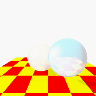
Like most rendering systems we will implement the classic Lambertian + Phong lighting model. This adds diffuse and specular light. The idea behind splitting lighting into two parts enables us to handle some important phenomena in a way that is far more performance friendly than the unified lighting model. Diffuse light is smooth shading that appears on objects which have any roughness to them. In reality almost all objects have some roughness which causes diffused illumination, and most objects are mostly diffusely lit. Glossy objects exhibit specular highlights. This is the effect where a glossy object will appear to have a sharp highlighted area. Putting these two together yields an image like below.


A note should made about the shadows. In rasterization systems like those used for real-time rendering shadows are a thorny issue. They must be handled with special algorithms. In a raytracing engine such as the one here, the shadows are handled incredibly elegantly. When a surface is hit, a ray is cast from the hit point toward the light. If it hits a surface on the way then we simply don't light the surface. Now, if we were to talk about creating soft shadows (a side effect of using more realistic lights which have actual area instead of being infinitely small points)...

Most scenes look rather flat being lit by a single light. Surface in the real world are often lit by many light sources (amongst lots of other lighting phenomena). Lighting from multiple light sources creates a much better effect. Using a second light from above yields the image below.


The effect of the scene is far better than before.

Multiple lights are all good, but another problem is that every object uses the same lighting equations. Many things can be done with the standard phong lighting model, but objects in the real world often exhibit far more complicated lighting effects.

A simple test of multiple lighting models is to add an easy-to-implement second model. The model I chose is called the trilight model. The idea behind this lighting system is to take three colors and use the existing values calculated for the phong equations and combine them in a new, flexible way. This can create back and rim lighting effects easily, by tweaking the three colors of the material. The previously blue ball is shown below with a red rim lighting effect. What this means is that the rim of the ball which is perpendicular to the light will have a red tinge to it.


In the future, much more complicated and realistic lighting models can be used (oren-nayar, for instance, or ward). Texturing is coming up, and that will add a lot of possibilities for more realism, especially with our ability to swap in new lighting models.